Explain Flow Diagram Of Vcr System Compression Vapour Schema
Refrigeration schematic diagram Schematic representation of the modifications introduced in the vcr 2/1 -process operation of a vcr system [6]
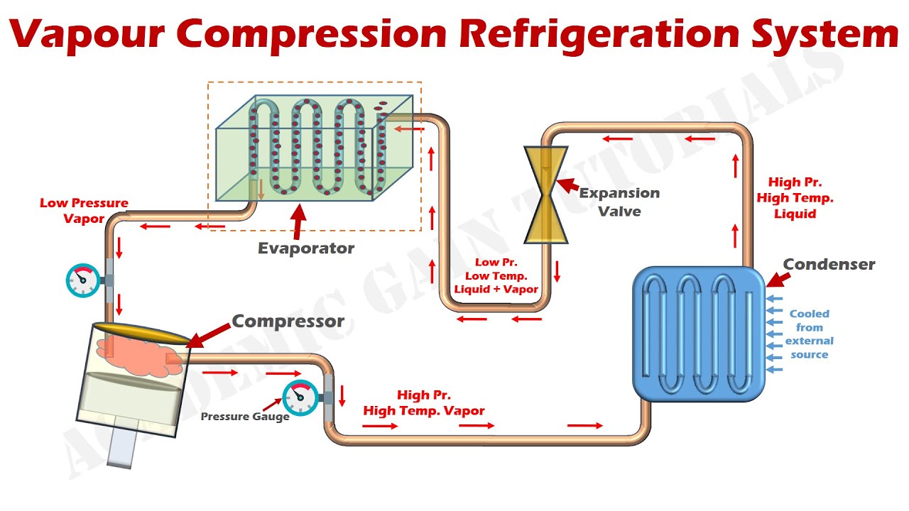
Flow Diagram of VCR System | Download Scientific Diagram
Simple vapour compression refrigeration system Schematic diagram of a proposed vcr system Schematic diagram of a simple vcrs.
Flow diagram of vcr system
2: two-stage cascaded vcr system developed in the study.What is vcr? Schematic diagram of experimental vcr system.Vcr diagram.
Vcr modelling freshwater assisted framework generateT-s diagram of vcr cycle P-h diagram of vcr cycle-process operation of a vcr system [6].

Figure f.4 schematic of a vcr system with a counter-flow heat exchanger
2: main components of vcr cycle [37].2: main components of vcr cycle [37]. How a vcr worksSimple vapour compression system.
Schematic diagram of vcr with instrumentations.Vapor compression system Flow diagram of vcr systemSimple vapour compression refrigeration cycle on p-h diagram.

Schematic diagram of a simple vcrs.
Schematic layout of the cascade vcr system(a) detailed schematic diagram of the vcr current source. (b 1: an idealized, single-stage vcr system.Refrigeration compression vapor function conditioning absorption explained.
National vcr day. dust it offSchematic diagram of a two-stage vcr system. Vcr refrigerationSchematic diagram of experimental vcr system..

Refrigeration control circuit diagram
(a) vcr simple cycle; (b) vcr cycle with internal power regenerationCompression refrigeration vapor refrigerator vapour evaporator expansion condenser timetoast Vcr cascadedCompression vapour schematic vcr vapor.
How vapor compression refrigeration system worksVcr current detailed linearized .

Schematic layout of the cascade VCR system | Download Scientific Diagram

Schematic diagram of a simple VCRS. | Download Scientific Diagram

VCR Diagram | PDF

Schematic diagram of VCR with instrumentations. | Download Scientific

Flow Diagram of VCR System | Download Scientific Diagram

Vapor Compression System | Compression Cycle | ARANER

National VCR day. Dust it off - The Amphitheatre Forum - TigerNet

Processes | Free Full-Text | Performance Analysis and Working Fluid